


Suppress Static Sparks to Protect Sensitive Coatings
- Published: October 20, 2023
Static Sparks Cause Thermal Damage Causing Holes or Voids in Thin Coating
By Dr. Kelly Robinson, Founder, Electrostatic Answers
There is need to control static levels in manufacturing operations for three reasons; safety, product quality and operational reliability. Static sparks can ignite flammable vapors and shock operators. Static sparks can damage sensitivity coatings. And, static charges can cause coating defects in sensitive coatings. Also, in sheeting operations, charges can cause sticking and jamming resulting in machine downtime.
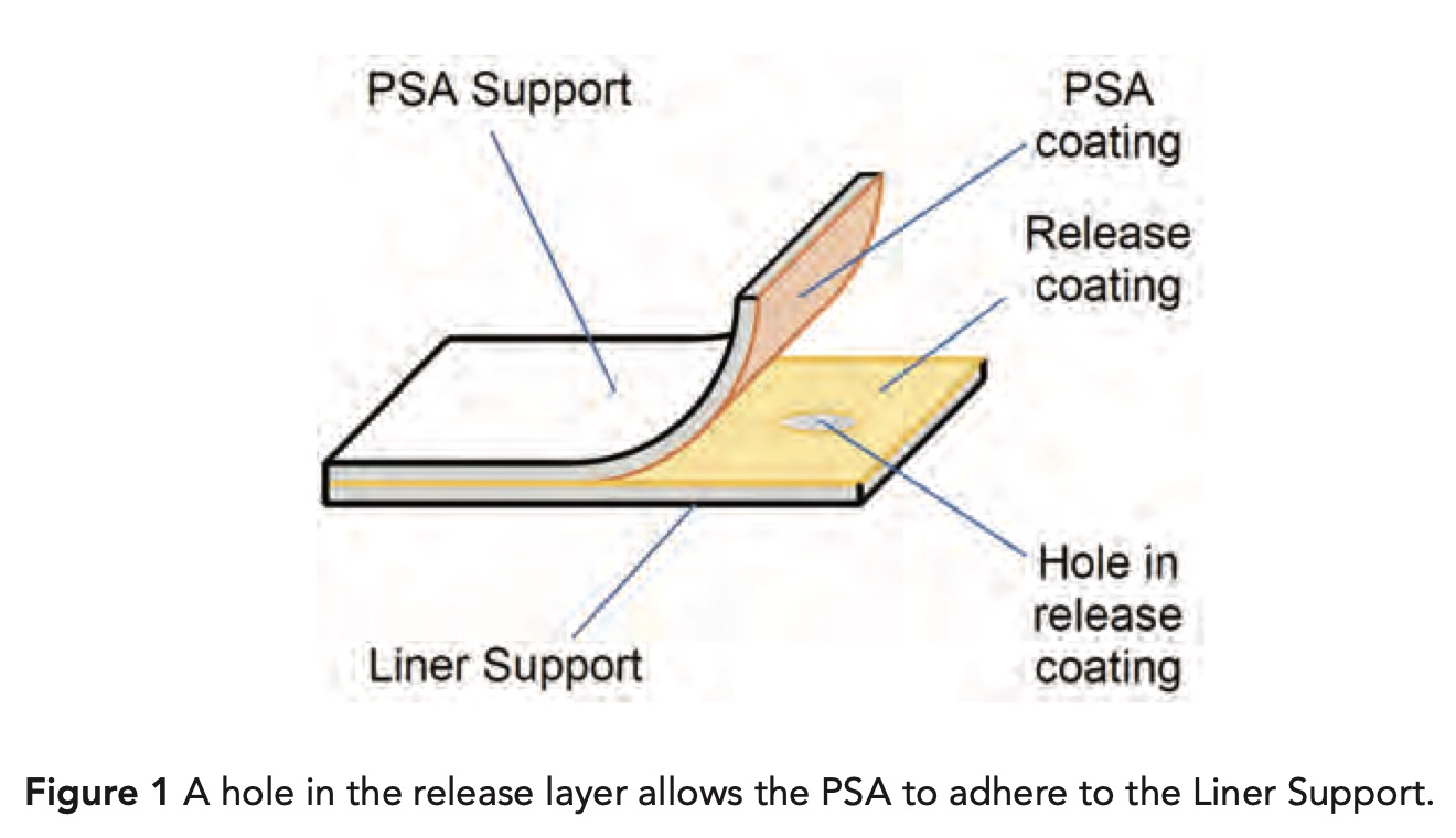
Static risks to product quality are especially important for sensitive products like silicone release liners. The release layer in Figure 1 usually has a coating thickness in the range 0.1 um to 1.0 um, which is very thin. This release liner enables the pressure sensitivity adhesive (PSA) to reliably peel from the liner.
Thin coatings are prone to thermal damage from static sparks resulting in holes or voids. The hole in the release liner in Figure 1 could be caused by a static spark during the manufacture of the liner any time after the release layer was coated. Static sparks are only one of several root causes for holes in a release coating. Other root causes include bubbles or foam in the coating solution, contaminates in the coating solutions, contaminates on the Liner Support and dirty coating rollers. Producing high-quality release liners requires clean manufacturing operations.
Excellent static control is required for exciting, ground-breaking products having new chemical and electrical functionalities such as shelf-life indicators (e.g., oxygen sensing, moisture sensing) and coated circuit components (e.g., diodes, transistors). In addition to thermal damage, static sparks can change the chemistry of a sensitive coating resulting in functional failure. A static spark is like a miniature corona treater that, among other things, oxidizes a small spot on the web. Product failures can occur even with no apparent, physical damage such as a hole, void or burn mark.
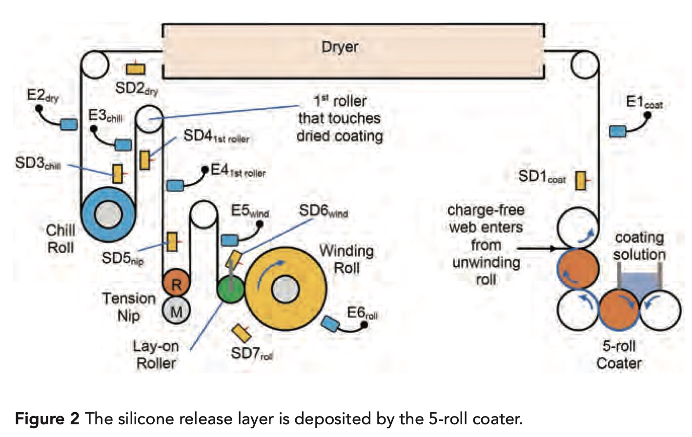
Prevent static sparks that can damage the silicone release layer coated in Figure 2 by implementing good static control in the critical zone from the coater to the winding roll. Keep electrostatic fieldmeter (ESFM) readings in the Low Static Green Zone below ±5 kV/in to suppress static sparks that can damage the release layer1.
The coater in Figure 2 has good static control upstream of the coater so that a charge-free web enters the 5-roll coater. Take a few key ESFM readings, E1coat through E6roll, using a handheld fieldmeter to decide if static control performance is OK, or if improvements are needed.
ESFM reading E1coat in Figure 2 tells us if the coater adds a significant amount of static charge to the web. If E1coat exceeds ±5 kV/in, install powered static bar SD1coat exiting the coater facing the back, uncoated side of the web.
Static bar SD1coat is prone to failure by contamination from mist from the 5-roll coater. Mounting SD1coat facing the uncoated web surface will help decrease the amount of contaminating mist near the static bar. Install an air-assisted static bar with clean, filtered air exiting from inside the dissipater housing flowing over the ionizing pins. This filtered air helps keep the ionizing pin clean extending the service life of the static dissipater.
ESFM reading E2dry in Figure 2 tells us if the dryer adds a significant amount of static charge to the web. Keep E2dry below ±5 kV/in. If needed, install powered static bar SD2dry exiting the dryer facing the back, uncoated side of the web because this is where the charge is deposited by touching the dryer idler rollers.
ESFM reading E3chill in Figure 2 tells us if the chill roll adds a significant amount of static charge to the web. Keep E3chill below ±5 V/in. If needed, install powered static bar SD3chill exiting the chill roll facing the back, uncoated side of the web because this is where the charge is deposited by touching the chill roll.
ESFM reading E41st roller in Figure 2 tells us if the first roller that touches the freshly dried coating adds a significant amount of static charge to the web. This first roller, to touch a freshly dried or cured layer, often adds a significant amount of charge. Keep E41st roller below ±5 kV/in. If needed, install powered static bar SD41st roller exiting the first roller to touch the freshly dried coating facing the coated side of the web because this is where the charge is deposited by touching the roller.
ESFM reading E5wind in Figure 2 tells us if the tension nip adds a significant amount of static charge to the web. Keep E5nip very low, below ±2 kV/in, because the web entering the winding roll should carry very low charge. If needed, install powered static bar SD5nip exiting the tension nip facing the web surface that touched the rubber or polymer coated nip roller because this is where the charge is deposited by the tension nip.
ESFM reading E6roll in Figure 2 tells us how much static charge is stored on the winding roll. Keep E6roll below ±5 kV/in. If the reading is too high, install SD6wind facing the winding roll exiting the lay-on roller. Since this dissipater is mounted to the lay-on roller frame, this static dissipater is prone to failure caused by vibration. Use a dissipater that is mechanically strong. Look for a static bar design that has components epoxy-cast in a fiber-glass u-channel.
Install static dissipater SD7roll in a fixed location outside of the rotation zone of the winder turret. Static bar SD7roll must be a long-range static bar that maintains reasonable neutralization efficiency at the start of a new roll with just a few laps on the winder core. Together, SD6wind and SD7roll will effectively dissipate charge on the winding roll.
Suppress static sparks to protect sensitive products by keeping electrostatic fieldmeter readings below ±5 kV/in. If needed, improve static control using best practices.2 For static dissipaters installed near coaters for silicone release liners, use air-assisted, powered static bars where clean, filtered air exits from inside the dissipater housing flowing over the ionizing pins.
- https://www.pffc-online.com/static-beat/15664-assess-static-risks-using-electric-fields
- https://ieeexplore.ieee.org/stamp/stamp.jsp?tp=&arnumber=9915453
About the Author
Dr. Kelly Robinson writes on static issues occurring in converting processes. Robinson founded Electrostatic Answers, has 40+ years of experience in industrial problem-solving and was named Top Manufacturing Consulting Services Provider 2023 by Managing MFG. He can be reached at Kelly. This email address is being protected from spambots. You need JavaScript enabled to view it..