


Unwind and Rewind Guides: Design and Installation Considerations
- Published: March 22, 2023
What are Terminal Web Guides?
Terminal web guides are devices used at the entry and exit of a roll-to-roll machine to appropriately align the web to the desired cross machine location. Entire roll of the web, on the unwind/rewind stand, is moved along the cross-machine direction for the proper alignment.
There are several names or terms commonly used for these terminal guides including: shifting stand, shifting base, shifting sidelay, uncoil and recoil, payoff and tension reel, and roll positioning stands. In an unwind web guide the wound roll is positioned so that the web is fed into the machine at the right location. While in a rewind guide, the wound roll on the stand, chases the web so that the web is wound on the roll in the right position despite movement in the incoming web. Even though both these web guides appear to behave the same way there are some important differences, especially with installation and control system design. Appropriate design of a terminal guide should include proper mechanical design and control system design based on the process parameters. This document is intended to provide information that would help designers.
Unwind Guiding
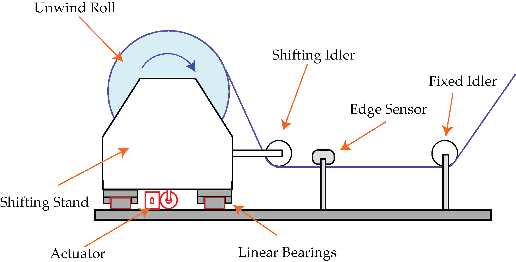
With an unwind guide, the entire unwind roll assembly supported on a stand is moved in the cross machine direction. Typically the stand is mounted on precision low friction linear bearings and moved with an actuator. A sensor is installed on the fixed machine frame and is typically located just downstream of the last idler that shifts with the unwind stand. The feedback from the sensor is used to move the unwind stand so that the web is at the desired cross machine location within the roll-to-roll machine. Following are list of items to check for proper installation of unwind guides:
- Ensure that the sensor is fixed and does not move with the unwind shifting stand.
- Ensure that the sensor is located just downstream of the last shifting idler on the unwind stand.
- Install the sensor as close as possible to the last shifting idler.
- Install at least one shifting idler on the unwind stand so that the diameter variation does not cause plane change at the sensor.
Rewind Guiding
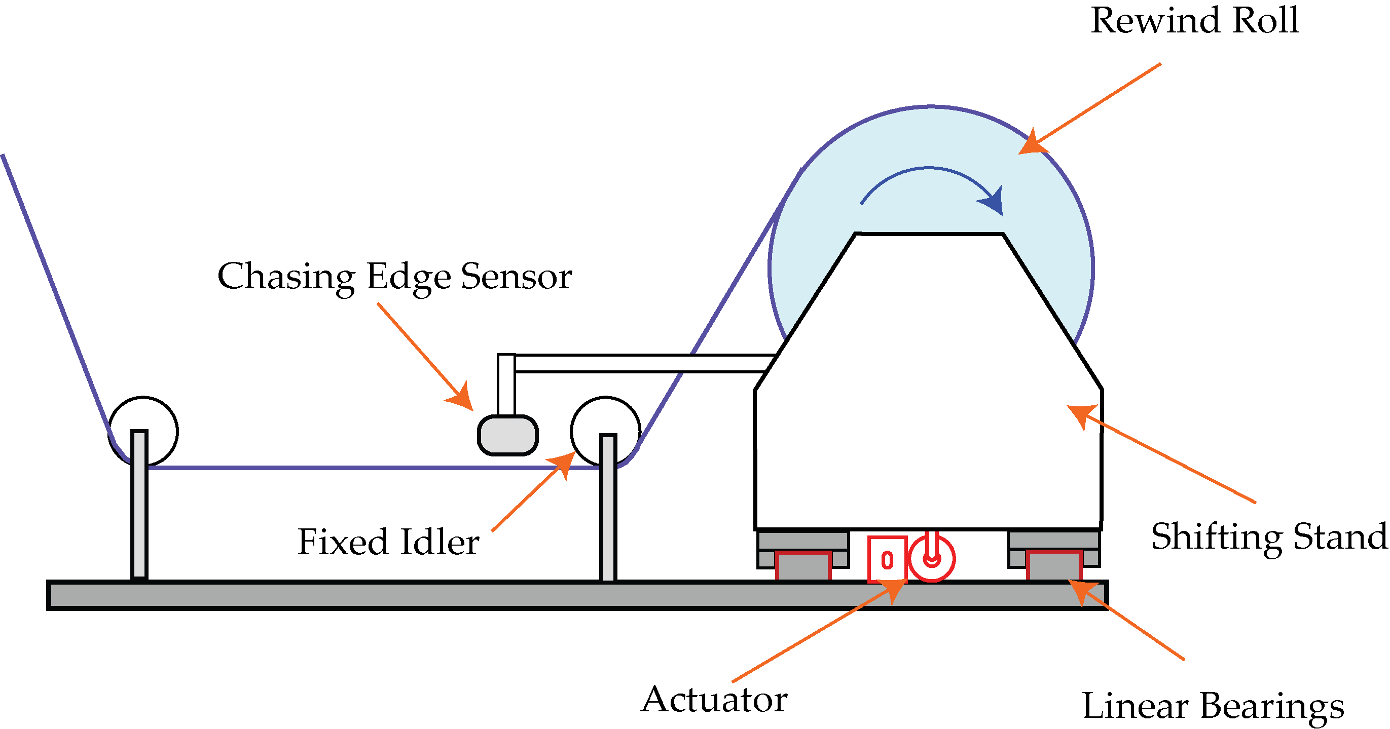
In rewind guiding, the winding roll chases the web and it is technically not guiding the web. The sensor is mounted to the rewind stand so that when the stand translates the sensor also moves. The purpose of the control system is to keep the relative position between the incoming web and the rewind stand constant, so that the resulting wound roll is straight. By installing the sensor on the translating rewind stand, a measurement of the incoming web relative to the stand is available. However, if the sensor is installed to the fixed machine frame the relative position between the web and the stand would be lost. This will not close the feedback loop. Hence for rewind applications, the sensor should always be installed on the moving rewind stand. The checklist for proper rewind guiding installation include:
- Ensure that the sensor is mounted on the moving rewind carriage.
- Ensure that the fixture for mounting the sensor is stiff.
- Ensure that the sensor is installed to observe the web just upstream of the last fixed idler before the rewind stand.
- Install the sensor such that it is as close as possible to the last fixed idler upstream of the rewind stand.
Mechanical Design Considerations
Mechanical design is critical since large mass is moved in this type of web guide; especially the mechanical design requires consideration for the speed, acceleration, thrust, structural rigidity, friction, etc.
Mechanical Structure Stiffness and Rigidity
The main consideration for the mechanical structure relates to the structural rigidity of carriage that supports the roll. Poorly designed carriages can cause significant vibration and mechanical resonance if the stiffness of the system is not designed properly. Specifically, the natural frequency of the guide structure along with the roll mass should be designed to be well over the natural frequency of the control system to avoid any mechanical resonance. For a terminal web guide the natural frequency of system is similar to a mass-spring system which is given by
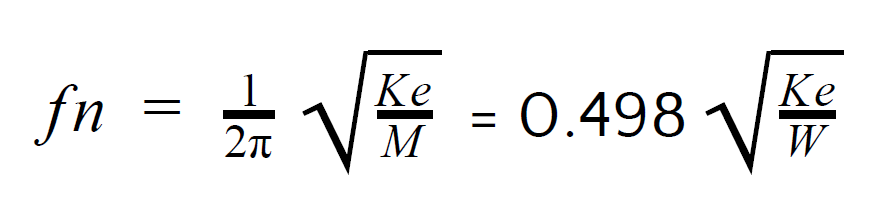
where Ke is the equivalent stiffness of the terminal guide structure, M is the mass of the terminal guide structure along with the roll (W is the weight), and fn the natural frequency of the terminal guide structure in Hz. As seen from the natural frequency equation, it is important to have a stiffer mechanism when a larger mass is needed to be moved.
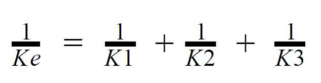
Apart from the stiffness of terminal guide structure, the design should also pay attention to the stiffness of the actuator, the actuator mounting or any support plate for mounting the actuator. These individual component stiffnesses contribute to the equivalent stiffness which can be modeled as equivalent stiffness of springs in series. It is evident that the least stiff element is going to have a significant influence on the overall effective stiffness of the assembly.
Natural frequency between 25 Hz to 50 Hz would be an ideal choice for the terminal web guide since most control systems for these terminal guides are typically designed to have a natural frequency between 8 Hz to 15 Hz.
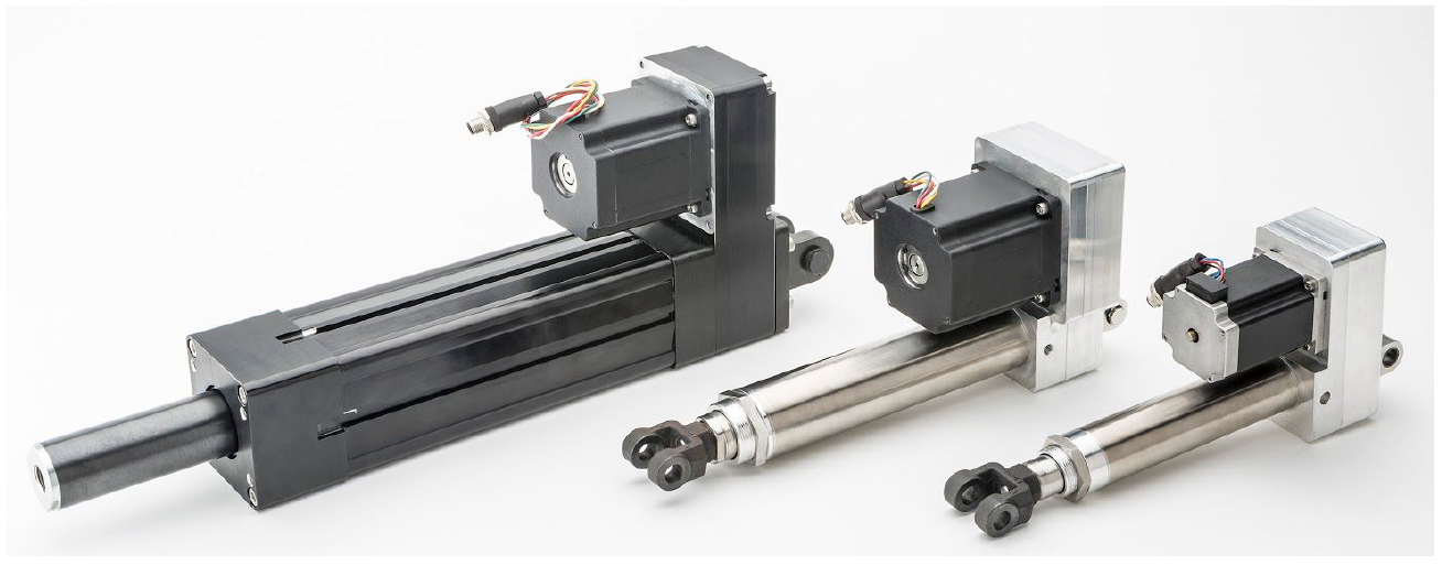
Actuator Type
Legacy actuators for unwind and rewinds were hydraulic and at times pneumatic cylinders. However with the advances in controls and drives, the state-of-the-art stepper and servo actuators can provide benefits such as smooth response at variable speed as well as full force/thrust at zero speed, while eliminating the need for plumbing and the possibility of product contamination with hydraulic fluid leak. It is critical to choose an appropriate actuator based on the desired dynamic response by considering the mass to be moved. Moreover the stiffness of the actuator (piston/rod and the mounting) should also follow the same constraints as the stiffness of the carriage to avoid any issue with resonance.
Most electro-mechanical actuators convert the rotary motion of a motor into linear motion at the actuator using some kind of a screw/nut mechanism. Typically a rod style actuator is used where the nut is connected to a rod that extends and retracts to transmit power. Low cost actuators typically employ a simple lead screw mechanism with a metal or plastic nut. These actuators cannot provide high thrust or high dynamic response because of the nut wear that limits the thrust and creates backlash. Higher end actuators would employ ball screws (with recirculating balls) or roller screws or planetary roller screws that provide higher thrust as well as lower backlash for superior dynamic performance. These high end actuators may also have anti-backlash (spring loaded nut) and anti-rotation (splines to prevent nut rotation) provisions builtin.
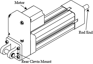
In unwind and rewind guiding applications two types of motor mounting options are common. In the reverse parallel configuration the motor shaft and the screw axis are not collinear, but they are parallel to each other. This is a compact configuration with the overall actuator length between the mountings to be smaller than the other inline configuration. Belt/timing pulleys (with 1:1 to 8:1 ratio) are used to transmit the torque from the motor to the screw. Inline mounting of the motor and the screw is also common but the overall length of the actuator is longer. Gear boxes are typically employed with inline mounting of the motor and the screw. The motor shaft and the actuator screw axis are collinear.
Using the belt ratio between the pulleys (or gear box ratio) along with the screw pitch, mechanical advantage is gained to provide high thrust at the actuator. This mechanical advantage allows the use of lower torque motors but since the power transmitted is the same, higher trust can only be provided at lower speeds. By increasing the output power of the motor, higher thrust can be transmitted at higher speeds.
Motor Type
While moving a large mass simple DC motors may not be an ideal choice. A servo motor or a stepper motor with advanced drives (microstepping) and controller (motion profiles) may be necessary. Servo motors provide the highest performance since the thrust can be maintained at high speeds. However, tuning a servo motor is load dependent and such a tuning might need to happen in the field to ensure proper performance.
A properly designed stepper motor system (speed and position motion profiles) can provide comparable performance at lower cost. By taking advantage of the fact that stepper motors can provide high torque at low speeds (less than 1000 rpm), when compared to a similarly sized servo motor, mechanical gearing and lead screw pitch can be designed to meet the thrust/speed requirements of a terminal web guiding system. By utilizing advanced stepper drive and controller capabilities such as microstepping, current chopper control, speed ramping, anti-resonance modes, load based current control, etc., the low cost stepper can provide similar performance of a servo motor for terminal guide actuators.
The main consideration irrespective of the type of motor is the inertial effect of moving a large mass and sudden direction changes required for web guiding. Appropriate compensation for backdriving or back emf generated during deceleration should be implemented. With advanced stepper and servo drives, coasting can be avoided and breaking by means of deliberate deceleration can help reduce regeneration problems. Additionally, a linear power supply or a regenerative power supply can absorb some of the energy generated during deceleration. Regeneration breaks can also be used to dissipate the excess energy while a switching power supply is used.
Actuator Sizing
The actuator must be sized appropriately to ensure that enough thrust is available from the actuator to move the mass at the desired speed. The thrust needed should overcome the breakaway force due to the bearing friction as well as to accelerate the mass to achieve desired dynamic response.
Breakaway Force
The breakaway force is essentially the force required to move the mass from rest to a non-zero velocity. This is the static friction force which is a function of the coefficient of friction and the weight of the carriage along with the roll of the web.
The coefficient of friction depends on the type of bearing used and the relative alignment of the sliding/rolling surfaces. It is typical to assume 0.25 as the coefficient of friction for purely sliding surfaces. These include plain linear bearings on appropriate metal shafts with certain surface finish or roughness. These are not common with terminal guides and should be avoided especially with large loads. Since rolling friction is much lower than sliding friction, ball or roller bearings are commonly used in the linear bearings for terminal guide carriages. These have significantly lower coefficient of friction ranging from 0.01 to 0.08. Seal drag, lubrication viscosity and any pre-loading can increase the coefficient of friction for roller or ball bearings. Apart from the coefficient of friction of individual linear bearings, the alignment of the various bearings with respect to the rod/shaft/profile on which the bearings slide has an effect on the breakaway force. Any misalignment with the installation of the bearing and the respective slide surface could contribute to additional friction. Hence the overall breakaway force is a function of the type of bearing as well as the relative alignment of the individual bearings with respect to the carriage.
The breakaway force can be directly measured by loading the carriage with the roll and measuring the force required to move the carriage as it moves over the linear bearings. A simple spring (push or pull) weight gauge can be used to measure the breakaway force. And most gauges would have a provision to measure the maximum force.
Force for Acceleration
Apart from the force to overcome the breakaway force, additional thrust is required to accelerate the mass to meet the desired performance requirements. Based on Newton's law the required thrust is directly proportional to the mass and the desired acceleration. The desired acceleration can be obtained with the knowledge of the magnitude and the type of disturbance expected. Most web guides, and specifically terminal web guides, are mainly intended to remove steady state disturbances. The dynamics response for such disturbances are not that demanding compared to dynamic disturbances such as a sinusoidal disturbance.
One parameter that is often misused is the actuator correction speed. The speed is irrelevant if the web guide cannot accelerate fast enough to get to the maximum speed. Web guides typically make small corrections with quick change in direction. In these scenarios, acceleration is an important factor.
For example, a sinusoidal disturbance of magnitude 5 mm (approximately 0.2 in) at a frequency of 2 Hz requires the actuator to have an acceleration of at least 790 mm/sec^2 (7.7 in/sec^2) to reject the disturbance. The same magnitude disturbance at 0.5 Hz frequency would require only 49 mm/sec^2 (1.94 in/sec^2) of acceleration. Hence it is important to not only know what the maximum speed of the actuator is, but also the maximum acceleration possible.
Finally, the acceleration is an important factor when using the terminal guides with oscillation application. In these applications the guide is deliberately made to oscillate to prevent gauge band variations across the width. In such applications both acceleration and speed must be chosen properly based on the power and thrust output of the actuator.
A good understanding of the application requirement will enable designers to properly size the actuator based on both the breakaway force and the acceleration requirement.
Actuator Mounting
Actuator mounting is an important part of the terminal guide design. As mentioned earlier, the stiffness of the actuator and the actuator mounting is critical to avoid resonance issues with terminal web guides.
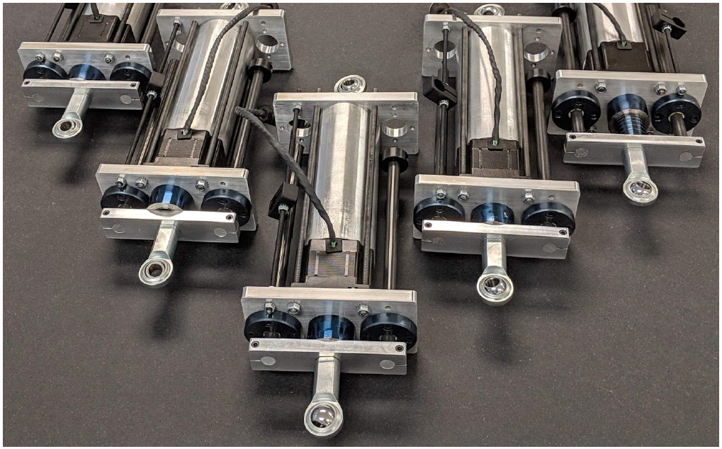
Two common mounting include, fixed and floating mounting. In a fixed mounting the actuator is mounted rigidly to a fixed base and the rod end of the actuator is also mounted rigidly to the moving carriage. This type of mounting can provide the best performance since there is no play in the mounting. However, the alignment of the mounting becomes extremely critical in the remaining five degrees of freedom. The most common problem with this type of mounting is the binding of the actuator due to misalignments. This biding can cause side loads on rod style actuators leading to premature failure. To reduce the effect of side loads and binding issues some actuators have parallel guideways or raceways to absorb the side load and prevent it from reaching the actuator rod.
Floating mounts for the actuator reduce the alignment issues by providing an additional degree of freedom in the mounting. An eye mount or a clevis mount is used so that a pin can connect these mounts to provide the additional degree of freedom in alignment. This additional degree of freedom allows the actuator to float or pivot about the pin when the actuator extends and retracts. It is common to have both the connections (between the actuator and the moving carriage, as well as between the actuator and the fixed machine frame) to have a floating/pivoting mount; however in some cases one of them might be a fixed mount and the other floating. Some of these might also have a spherical eye, which provides another degree of freedom for mounting.
One of the main issues with the floating mount is the play in the connection. Any play in the connection can significantly reduce the achievable dynamic response. One other issue comes with improper installation. Care needs to be taken to ensure that the pin axis is installed properly to allow for the actuator to pivot in the correct plane. It is not uncommon to see such improper installation. This is mainly seen with spherical eyes since that extra degree of freedom provided by the spherical eye causes confusion with the plane of motion.
Summary
Several important aspects of a terminal guide design have been discussed in this article. With this understanding the designers and practitioners can get the best possible performance for their application needs. Roll-2-Roll Technologies is here to help with any of your design needs, questions and concerns about terminal guide installation.
Please call us today (+1-888-290-3215) to find out more about how we can help with your new unwind/rewind guiding system installation or upgrade.