


Static Control for Flexographic Printing
- Published: July 06, 2020
Control static to prevent sparks where the printed web exits the central impression drum.
By Kelly Robinson
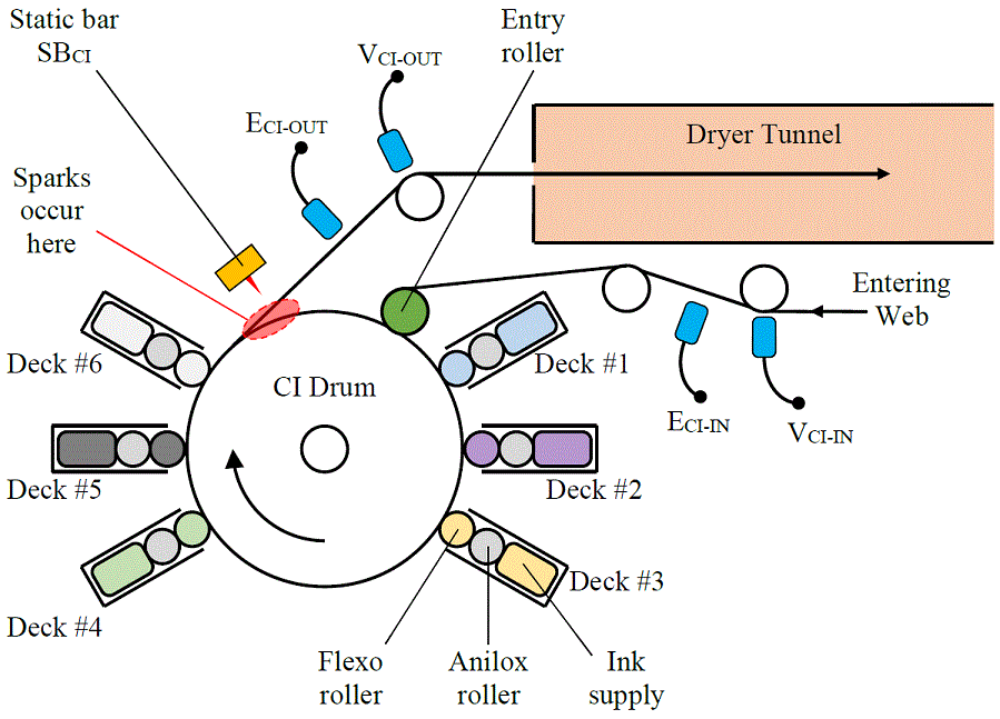
Figure 1: Central Impression (CI) Drum of a 6-deck flexographic press
Flexographic printing presents several unique static control challenges because, we can dissipate static on the printed web only after it exits the Central Impression (CI) Drum. And, the main problem is that static ignitions occur where the web exits the CI drum.
Flexographic printing has several different flavors. One common method in Figure 1 is to print a web wrapped on the large, Central Impression (CI) Drum. These large presses usually have four to ten print decks. The press in Figure 1 has six decks. Each deck has a flexographic pad with the pattern to be printed. This flexible pad, which is wrapped on a roller, prints by pressing against the web. An anilox roller delivers ink to the pad from the ink supply. The limited amount of flammable ink near the CI drum is good because large, destructive fires are uncommon on flexographic presses.
Still, static ignitions do occur where the web exits the CI drum. Static charges on the printed web spark to the CI drum. These sparks can ignite flammable solvents. To prevent these ignitions, we need to know how static gets on the web so that we can get rid of it, or at least keep it low enough to prevent sparks.
Table 1: Flexographic press static control best practices
|
# |
Element |
Static Control Description |
|
1 |
Entering web |
Charge-free web enters CI drum |
|
2 |
Entry roller |
Minimize charging from Entry Roller |
|
3 |
Flexo pads |
Only inked flexo pads touch web |
|
4 |
Last print deck |
Prohibit solvents from last print deck |
|
5 |
Static bar SBCI |
Install static bar exiting CI Drum |
|
6 |
Verify |
Measure static to verify good control |
Six Best Practices for Preventing Static Ignitions of Flexographic Presses
- Entering Web – The web entering the CI Drum in Figure 1 should be as charge-free as possible. Practice good static control upstream of the CI Drum along the web path all the way from the unwinding roll to the CI Drum. Two common sources of static charging upstream of the CI Drum are the unwinding roll and the corona treater. The unwinding roll can store a large amount of static from the operation where the roll was wound. Dissipating this static on the unwinding roll required two, powered static bar.
The printed surface of the web is commonly treated with a corona treater to improve ink wettability and image adhesion to the web. Along with these benefits, corona treaters can also deposit a large amount of static on a web. Install a static dissipator on the web exiting the corona treater.
- Entry Roller – The Entry Roller in Figure 1 ensures that the web lays flat on the CI Drum. At high web speeds, air bubbles can get under the web. These bubbles cause wrinkles and print defects. The Entry Roller presses the web against the CI Drum surface to prevent these wrinkles and defects. As with any nip roller, the Entry Roller can deposit large amounts of static on the web surface that touches the roller. And, with the web wrapped on the CI Drum, we have no way to dissipate this static until the web exits the CI Drum.
We can do two things to reduce static charging from the Entry Roller. First, use the lowest nip pressure that you can. Of course, we need enough pressure to maintain good print quality. Just use what you need and no more.
The other thing is to pick an Entry Roller that minimizes charging. The only sure way to do this is to evaluate several candidate roller materials. Most roller vendors can provide small, 2-inch by 2-inch coupons of candidate roller materials. Ask for a few samples and, in an off-line test, measure charging of the text coupons on a couple of webs that run on the press. Pick the material that has the lowest average charge on the webs. Often, polyurethane deposits less charge on webs than silicone rubber.
- Flexo Pads – Only inked flexo pads should touch the web. I know, this seems obvious. However, some operations save clean-up time by stopping ink delivery at the end of a run allowing the flexo pads to run dry. I strongly recommend against this practice. A dry pad is like a nip roller. Just like any nip roller, the dry flexo pad can deposit large amounts of static on the web. The better alternative is to pull back the inked flexo pads at the end of a run and clean them off-line.
- Last Print Deck – Flammable solvent vapor is the fuel for the fire. Eliminate the fuel and prevent fire. Do not use flammable solvents in the last print deck. For the flexographic press in Figure 1, do not use solvent based inks in Deck #6.
This is more complicated that it sounds. The last coated layer is often a protective overcoat or lacquer that covers the high-value printed image. The overcoat is often a thick, protective layer. So, this overcoat is often solvent based so that drying is faster. However, this thick, solvent coating also causes a high solvent vapor concentration exiting the print deck.
We can do two things. First, some jobs do not require that we use all of the print decks. In this case, we can make the last print deck one of the extra, unused decks. Apply the overcoat using one of the upstream decks. This gives the solvent vapors a chance to disperse before the web exits the CI Drum.
The second thing is to use a water-based overcoat. Of course, the dryer must be able to handle the heavy deposition of the water-based overcoat. Sometimes, the web speed may need to be slowed. I know that this is bad for machine productivity. However, static ignitions are also bad for machine productivity.
- Static Bar SBCI – Install powered static bar SBCI in Figure 1 above the web exiting the CI Drum. The idea is to stop sparks by neutralizing static on the printed web surface. While I do recommend installing this powered static bar, it might not stop all sparks. The web must separate from the CI Drum for the static bar to work. Sparks may occur in a small area after the web exits the drum and before the static bar can dissipate the static. The static bar makes this sparking zone very small. Still, there is a zone where sparks may occur. Installing this static bar is best practice #5. We still need to do best practices 1, 2, 3, and 4.
- Verify – Regularly measure static to verify that our static control measures are working. Verify that the web entering the CI Drum is nearly charge-free by measuring ECI-IN in Figure 1 with an electrostatic fieldmeter and VCI-IN with an electrostatic voltmeter. Reading ECI-IN should be taken on a web span midway between idler rollers. The reading should be less than ±5.0 kV/in. Reading VCI-IN should be taken where the web is wrapped on a grounded metal idler roller. The reading should be less than ±10 V per mil of web thickness. So, for a 2 mil (0.002 inch) thick web, reading VCI-IN should be less than ±20 V.
Verify that the web exiting the CI Drum is nearly charge-free by measuring ECI-OUT in Figure 1 with an electrostatic fieldmeter and VCI-OUT with an electrostatic voltmeter. Reading ECI-IN should be taken on a web span midway between idler rollers. The reading should be less than ±2.0 kV/in. Reading VCI-IN should be taken where the web is wrapped on a grounded metal idler roller. This reading should be less than ±10 V per mil of web thickness. So, for a 2 mil (0.002 inch) thick web, reading VCI-IN should be less than ±20 V.
Our over-arching static control goal is to prevent sparks where the web exits the CI Drum. To do this, we need to practice good static control along the web path all the way from the unwinding roll to the exit of the CI Drum. Implementing these five best practices should stop sparks.
About the Author
Kelly Robinson, PE, Ph.D., is the owner of Electrostatic Answer, an engineering consulting company dedicated to eliminating injury and waste from static electricity. He can be reached directly at Kelly.Robinson@ElectrostaticAnswers.com.