
Roller Geometry | What Is Your Roller’s True Shape?
- Published: June 23, 2017, By Stephen Huff and Mark Miller
How does a roller’s shape influence a coated product and coating defects? The variation of a roller’s geometry can produce many web handling problems.
Roller geometry directly affects the way a web is handled through a machine. Common roll tolerances address roller diameter, taper, and total indicated runout (TIR). But what do these variations really mean to the end-user? Specifically, how does the roller shape influence a coated product and coating defects an operator may experience.
Most line operators and engineers have a general understanding of these properties but not how they affect their product, let alone the proper way to measure these variations. A simple dial indicator cannot reveal the true concentricity of a roller.
This article will discuss roller geometry variation, its effects on web handling, and new-to-the-industry techniques to determine the “real” values for these variations.
Let’s start with the most common tolerances that are used with rollers. This list includes but is not limited to:
- Diameter
- TIR
- Runout
- Profile
- Surface Finish
- Crown
In addition, concentricity is specified and in very rare cases, cylindricity is called out. These tolerances are used to describe the variations from the specified roller geometries. If the geometric variances are too great, then web handling problems, such as wrinkling, stretching, bagging, repeating patterns, poor steering, and tension variation, can occur.
Most of the time there are only two variations that are specified when making rollers. These are diameter and TIR. These variances are common to most rollers because they are the easiest measurements to take. Just because they are conveniently measured doesn’t mean they are the most critical when it comes to predicting roller success. Coating success depends on precision, and roller precision isn’t simple. If the gaps between a coating head and a roller surface are not predictable and maintainable, then the coating will be riddled with defects.

TIR or Total Indicated Runout, usually measured with a dial indicator, only tells the measurer how round one slice of the roller is at the location where the dial indicator is contacting the roller. Using TIR as a guiding tolerance implies that the entire roller surface will have the same reading. This is simply not true. A camshaft is perfectly round at all of its bearing sites (see Figure 1). However, you wouldn’t want to use a camshaft as a backup roller.
And as shown in the camshaft image, rollers are typically checked in three areas across the face. With this amount of measurement, the discrepancy in the roller will not be recognized. The more descriptive measurement of a roller’s roundness is called concentricity, which looks at how round a roller is with respect to other surfaces such as a bearing journal. This is not a single TIR measurement with one dial indicator. This measurement requires multiple measurements with respect to one controlling surface. This idea is displayed in Figure 2.
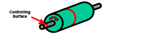
In this case, the concentricity callout would be referenced to the journal measurement slice (red band). First, the journal would be measured to find out how much runout it had. Next, the roller body would be rotated in the same setup and have its runout measured in several locations. These measurements would then need to be compared to each other. The lowest variance from the measurements would be subtracted from the highest variance from the measurements and that would determine the concentricity.

Concentricity can be a difficult measurement to perform correctly using manual methods such as multiple dial indicators. Newly developed advanced electronic measuring tools simplify the task. Multiple sensor heads simultaneously take runout readings and display the combined results. These systems are able to clearly show the roundness of your roller. In many cases, concentricity results can then help the roller owner predict success once the roller is ready to be reinstalled in their equipment. Concentricity measurements also can be used to diagnose hard to explain web behavior. Figure 4 below is an example of such a concentricity reading.
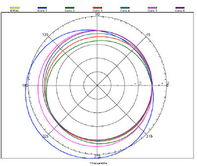
This plot clearly displays the relationship of six different roundness readings and how they relate to one another. In short, this is concentricity.
The other roller measurement commonly called for is roller diameter. This is measured in a number of ways including with Pi Tapes and micrometers. In most cases, three to five diameter measurements are made at even increments across the width of the roller face. Many users would take these numbers and call them the roller diameter profile or taper. Taking a few diameter measurements across the face of the roller and saying that it is cylindrical is like taking one TIR measurement and pronouncing that the roller is concentric. In both cases, the measurer once again assumes that no variation happens between the data points.
In slot die coating, the diameter of the roll is critical. A slot die has a precision flat surface in the lip face that works with the roller to develop an exiting flow control region for the liquid to form a thin film. If this thin film is disrupted, film split occurs and the coated product has defects. So, what diameter is best? The larger the diameter, the flatter the surface to coat against. In hot melt adhesive product coating, a 14-in. (355-mm) diameter roll is typically suggested. But how best to measure the roller shape to ensure flatness at the tangential coating position?
The more descriptive tolerance that should be specified for geometric roller shape is known as cylindricity. This measurement describes how “cylindrical” a roller is from one end to the other. Cylindricity is found by taking numerous diameter measurements or slices and comparing the highest diameter measurement to the lowest diameter measurement across the entire roller face. The range between the maximum and minimum diameter measurements is the value for cylindricity. Like concentricity, properly determining the cylindricity of a roller can be quite time consuming when using conventional tools.
Once measured, the data will probably be inaccurate due to the limitations of the measurement tools themselves. Pi Tapes have a limited accuracy to +/- 0.002 in., and their repeatability between operators varies even more. Micrometers are good on solid surfaces but are very tricky to use on soft elastomeric roll covers. In either case, critical roller cylindricity information is usually lost due to measurement methods and poor resolution.
Advanced electronic measurement systems make cylindricity measurements as easy to take as concentricity measurements. With 0.0001 in. repeatability in the diameter and 0.060 in. cross roller increment resolution, large numbers of data points are presented as a continuous plot so that the roller owner can clearly see how cylindrical their roller is. The figures below are several examples of true profile or cylindricity measurements.
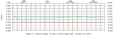
In the above case, the cylindricity is 0.0012 in. This is noted by the Max Dev. note at the bottom of the plot. (Max Dia. – Min Dia. = Cylindricity)
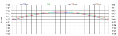
This plot shows a sine crown of approximately 0.025 in.
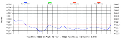
Lastly, this plot illustrates what can be missed by taking only 3-5 diameter measurements and assuming that the diameter remains the same between data points. Again, this system indicates that this roller has a cylindricity of 0.0043 in. Several points are within tolerance—but many more are not.
An automated continuous measurement system provides the only practical way of discovering a roller’s true shape. Any other traditional method of measuring these features is time consuming and can produce misleading results.
How Do These Tolerances Affect My Web and Equipment?
TIR, Run Out, and Concentricity issues can cause a number of irregularities in your coating process. Common problems caused by these irregularities include tension variations for sensitive webs, down web process variations, out of balance irregularities greater than 500 fpm, excessive bearing wear, vibrations, heat, and bearing fretting. Taper, Profile, and Cylindricity issues cause different irregularities such as wrinkling, buckling, creasing, and stretching of the finished coated products.
How to Use These Tolerances to Your Advantage in Coating
By understanding the tolerances and the effect precise roll geometry has on your coating process is an important part of maximizing your process performance and efficiency. Understanding roll geometry helps you reduce variations, determine die position, and adjust the gap to improve the quality of the coated product as well as more efficiently utilize the fluid and reduce costs.

CONCLUSION
In order to properly prepare rollers for web handling duties, it is important to know a roller’s true shape. The variation of a roller’s geometry can produce many web handling problems. Roller geometry variation must be tightly controlled to produce the greatest chance for success in its machine.
The only way to know a roller’s true geometric variation is to measure for concentricity and cylindricity. These variations are difficult to properly measure especially using conventional measuring devices such as dial indicators, Pi Tapes, and micrometers.
Advanced electronic measuring systems can produce accurate pictures of the exact geometric shape of your roller. These pictures can help diagnose roller problems and help to ensure that new rollers will be successful in your equipment.
ABOUT THE AUTHORS
Stephen Huff is director of engineering and technology at Imperial Rubber Products Inc., Chino, CA, developers of the TruShape measurement system. He is responsible for all manufacturing and quality functions. Huff is a leading technical authority in the roller industry, with extensive experience in coating and process development. He holds a BA in Engineering Physics from Westmont College in Santa Barbara, CA, and a BS in Manufacturing Engineering from California State Polytechnic University, Pomona. Stephen holds domestic and international patents in his field. He may be contacted for further information at This email address is being protected from spambots. You need JavaScript enabled to view it..
Mark D. Miller, author of PFFC's Coating Matters column, is a fluid coating expert with experience and knowledge in the converting industry accumulated since 1996. Mark holds a Bachelor's degree in Chemical Engineering from the Univ. of Wisconsin-Madison and a Master's degree in Polymer Science & Engineering from Lehigh Univ. and a Juris Doctor from Hamline Univ. Mark is a technical consultant and CEO of Coating Tech Service LLC. He has worked in web coating technologies and chemical manufacturing operations and is a certified Six Sigma Black Belt trained in both DMAIC and DFSS disciplines. Coating Tech Service provides process troubleshooting and project management for precision coated products. Mark has extensive process knowledge in high precision coating applications including thin film photo voltaic, Li-Ion battery, and optical systems technology. Mark has been integral to new developments and technology that minimize product waste and improve process scalability.