


Just Rolling Along
- Published: October 01, 2003, By Bob Eisele, Amacoil Inc.
Multi-speed, direct braked reversible motors. Valves and solenoids. Gear head assemblies. PLCs and other complex controls. Whether you design, operate, or maintain production machinery, you're probably familiar with the components and assemblies typically associated with linear drive systems. It's likely you're aware they can increase the complexity and cost of machine operation and maintenance, too.

For certain applications, a “rolling ring” linear drive system can eliminate most — and in some cases all — of these devices from production machinery. This simplifies operation and maintenance to save time and money and makes converting, assembly, and finishing processes more efficient. It also reduces the downtime typically incurred while performing routine operating and maintenance tasks such as changing gears or training personnel to operate electronic controls.
Simplify Setup
Printing, scoring, slitting, winding, slicing, spraying, welding — the production equipment used to perform processes like these often includes a linear drive system to move the tool head back and forth. Incorporating various types of linear drive assemblies into production equipment is routine for the designer, and equipment buyers generally accept the costs of training operators and maintenance technicians to handle screw-based and other types of common linear drive assemblies. But for certain applications, a routine approach to linear drive systems can lead to extra costs for components and unnecessary downtime of expensive production machinery.
The downtime results from typical tasks usually taken for granted: gearing down and up, replacing bent piston rods, replacing leaky seals, programming controls, and other procedures. Screws, hydraulic systems, timing belt drives, pneumatic assemblies — these are standard systems but do require special maintenance and operating skills. They also can require the added expense of stepper and servo motors, controllers, sensors, torque motors, encoders, clutches, and other components and assemblies.
However, if the linear motion required of the tool head is a simple, reciprocating motion, a rolling ring drive system may be used, which will simplify design, set-up, and operation of production machinery. Rolling ring linear drive systems provide automatically reciprocating linear motion without the complex controls, components, and programming. The drives provide backlash-free linear motion, and the only maintenance needed is periodic light lubrication of the drive shaft.

Additionally, a rolling ring system isn't screw-based. The shaft is smooth, without threads where dirt and debris could become trapped. This eliminates the chance of clogging or jamming. There is no need to interrupt production and stop the system to clean the shaft either. Nor do you need to slow down or stop the motor when changing drive head travel direction. Production machinery operating time is optimized while unnecessary interruptions are reduced.
Pulley System
To provide the smooth, automatically reciprocating linear motion required in many converting processes, a rolling ring drive system doesn't need clutches, cams, or gears. There is no programming, nor do you need costly motors and controllers. In fact, for many reciprocating motion applications, rolling ring systems don't need a dedicated motor. The system is driven off the main machine motor, connected via a simple, inexpensive pulley system.
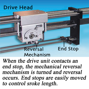
In a rolling ring assembly, automatic, instantaneous reversal of the drive head is controlled mechanically. Hardware “end stops” are positioned on the assembly. When the drive unit reaches an end stop, the mechanical reversal mechanism is triggered and reversal is instantaneous. Rolling ring systems also may be configured to ramp down/up before and after reversal. All changes to travel direction, and to some extent changes to linear speed, are automatic and completely independent of the drive motor speed and rotational direction. Reversal points are changed easily and quickly by moving the manually adjustable end stops.
The rolling ring linear drive operating principle is an intrinsically simple concept that uses a specially machined bearing assembly inside the linear drive unit to convert rotary input motion into backlash-free linear output. The user-adjustable angle of the bearing assembly, relative to the shaft, can be used to precisely control the drive head's linear pitch and travel direction. It's all done completely without complex electronic controls.
Rolling ring linear drive units are available separately or in custom-designed assemblies ready for installation into production machinery. The systems are used for a wide range of converting, finishing, and assembly processes including slitting, welding, coating, x-y table movement, rewinding, spreading, grinding, and spraying. The anti-backlash engineering of the bearing assembly makes it unnecessary to purchase extra anti-backlash solutions such as preloaded nuts, shims, or double enveloping gears. There is never any “play” between shaft and bearing regardless of shaft rotational direction or speed — including during reversal of the system.
For some reciprocating motion applications, winding for example, a rolling ring linear motion system does not require its own motor or controller. Instead, the assembly is linked to the main drive motor via a pulley system. The linear movement of the drive unit automatically is synchronized with the drive motor rotation without further adjustment — even if the drive motor speed changes.
Easy Maintenance
Ball screw systems and other linear drive systems offering automatic reversal of the drive nut almost always require extras such as special motors and controllers. If a process calls for a change in the linear pitch of the tool head, it can mean significant downtime to change gears or expensive electronics to adjust gear ratios. The operator training involved adds to overall investment and may make some processes less efficient.
Variable pitch rolling ring systems reduce a linear motion system's dependency on external, electronic controls and programming. Retrofitting an existing linear drive system with a rolling ring drive can simplify the design, operation, and maintenance of production machinery and reduce costs. Machine setup and operation is simpler, and a rolling ring system is more efficient to operate and easier to maintain.
Depending on the make and model, rolling ring drive assemblies can deliver up to 800 lb of axial thrust. Travel length may be up to 16 ft at speeds ranging to 13 ft/sec. Typical accuracy is to within ±0.005 in. Special options are available for accuracy to ±0.0004 in.
If an application allows the use of a rolling ring linear drive system in production machinery, you may be able to circumvent the normally required downtime and operating/maintenance costs associated with production machinery. Converting presses, web operations, and coating systems are candidates for a rolling ring drive assembly, which may improve the efficiency of production and reduce operating costs.
From Accidents Come Inventions
Rolling ring drive technology was invented in the late 1940s by a German factory worker named Joachim Uhing.
Uhing was working in a factory where much of the machinery was driven by a common drive belt/shaft arrangement. The belts and shafts ran across the ceiling. One day a belt slipped off its bearing and began moving linearly along the rotating shaft. When the belt reached the end of the shaft, it moved back the other way.
This is what got Uhing thinking about creating a linear drive using a similar “smooth shaft/bearing” principle.
The patents on the technology have expired; however, several manufacturers now produce rolling ring drives.
Bob Eisele is a customer support representative for Amacoil Inc., Aston, PA, handling sales and service inquiries from users and prospects of rolling ring linear motion systems. He has a technical sales and marketing background. Prior to working in the linear motion engineering field, Eisele serviced clients in chemical processing and engineering.
The views and opinions expressed in Technical Reports are those of the author(s), not those of the editors of PFFC. Please address comments to author(s).